Practical 3 - Hierarchical modeling
Objectives of this practical:
improve our understanding of OpenGL coordinate frames
deal with hierarchical scenes, such as an articulated kinematic chain
Pre-requisites:
it is best but not mandatory to have completed Practical 2 - Meshes and modeling
We provide a new set of files
viewer.py
color.vert
color.frag.
You will need the
transform.py and
core.py modules
provided in practicals 1 & 2, as we now use the full
Mesh, Viewer, Shader and load implementations provided by the core.py
file.
Finally, we provide a cylinder.obj
mesh file to build on in this practical.
Note: The Cylinder class loads positions and normals from the
cylinder.obj file. The normals are here send to the vertex shader as
the color attribute. That means the normal of a vertex is interpreted as its
color. Explain the obtained rendering of the cylinder.
Graphics transforms
Until now we have dealt with independent static sets of objects and have largely reasoned in clipping coordinate space or with minor variations thereof. As seen in the main course, more transforms are routinely used to structure the scene around a world coordinate system, where scene objects, lights and camera viewpoints can all be expressed in a common coordinate frame. Coordinate frames are structured as follows:
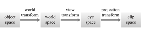
Object coordinate frame is a self-centered coordinate system where the geometry of objects is defined. The center of gravity of the object, or its central point of contact to the ground is typically set to be the origin.
The model transform is used to transform object coordinates to world coordinates, possibly reajusting its size. That transform is thus usually rigid (translation + rotation), possibly with a scale adjustment.
The view matrix is the transform from world space point to camera (or eye) coordinates. It is a rigid transform which essentially expresses where the camera is placed in the scene.
The projection matrix then transforms coordinates from eye coordinates to clip coordinates in \([0, 1]^3\), where the geometry can be processed for depth testing and clipping against the view frustum.
All these transforms are expressed as \(4 \times 4\) matrices, which are simply to be composed (multiplied) and applied to object coordinates in the vertex shader to directly get their clip coordinates:
#version 330 core
...
uniform mat4 model;
uniform mat4 view;
uniform mat4 projection;
...

void main() {
    // Note the order of composition of the transformations!
    gl_Position = projection * view * model * vec4(position, 1);
    ...
}
More information about these matrices can be found in Practical 1: 6. Projection Transform
In your viewer, the view and projection matrices are handled by the trackball. You simply have to define the model matrix for each of your scene’s object, to position these objects in the world coordinates frame.
Hierarchical transforms
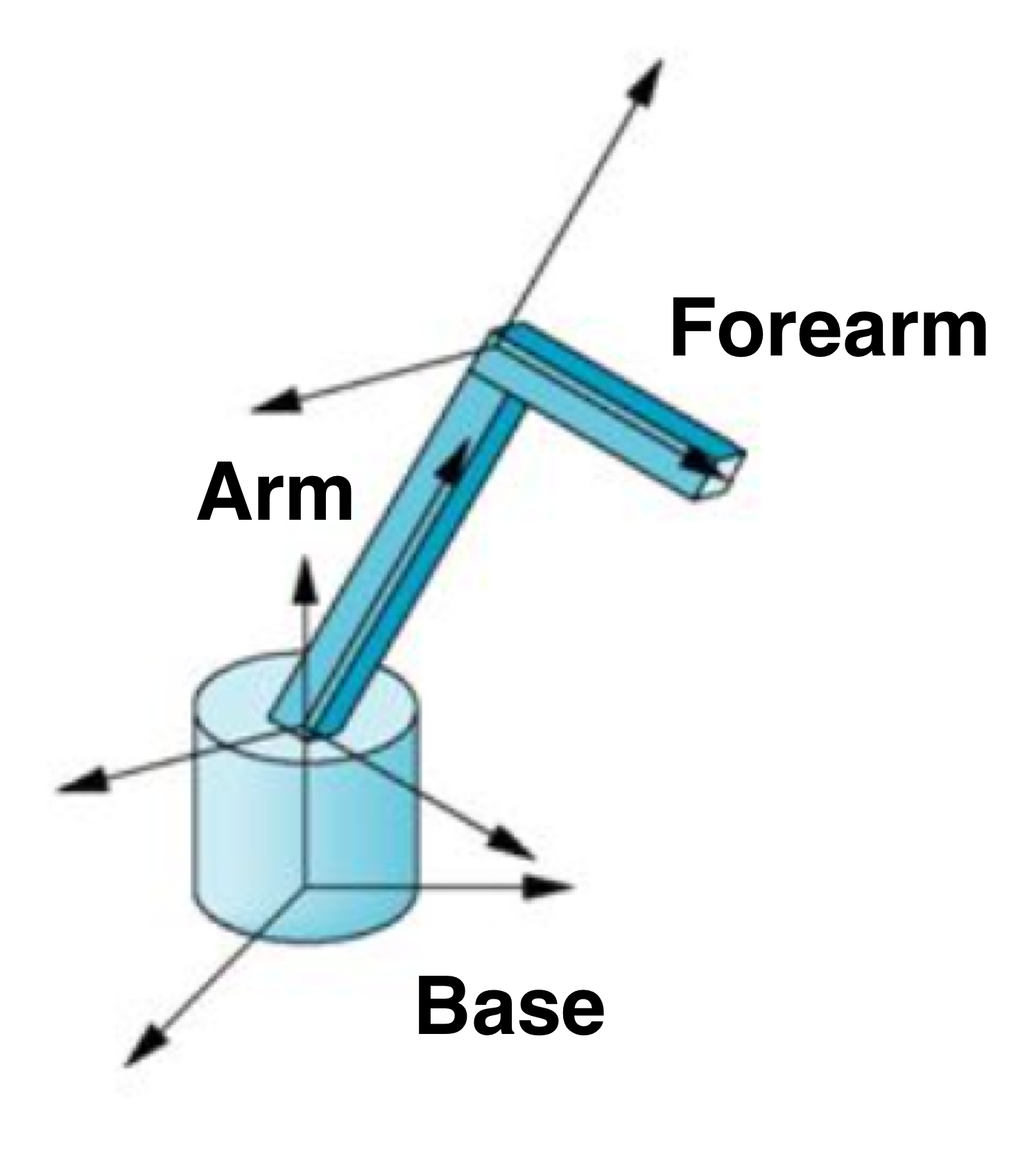
The transform chain above can be further refined, by noting that many objects are defined in hierarchical fashion, where sub-objects are naturally expressed in the local coordinate frame of a parent object. This is the case for articulated objects with kinematic chains, such as this robotic arm, with a rotating base, an arm and a forearm:
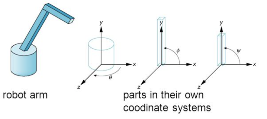
Each object in the hierarchy has its own coordinate frame, expressed relative to its parent. In the case of the robotic arm, each transform relative to the parent node is parameterized by a single rotation:
Transform nodes
A practical way of representing hierarchies is to add a new type of ‘transform node’ object in our application that:
is drawable (has a
draw()method)may have children: it contains a list of drawable objects
defines a new coordinate system relative to its parent, which affects all its children and descendants
Using this new drawable type, we can then represent our robot arm with some cylinders and adequately placed transform nodes. In computer graphics this is called a scene graph:
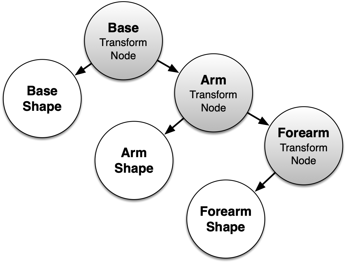
We can write a Python Node class implementing this definition,
given in core.py:
class Node:
    """ Scene graph transform and parameter broadcast node """
    def __init__(self, children=(), transform=identity()):
        self.transform = transform
        self.world_transform = identity()
        self.children = list(iter(children))

    def add(self, *drawables):
        """ Add drawables to this node, simply updating children list """
        self.children.extend(drawables)

    def draw(self, model=identity(), **other_uniforms):
        """ Recursive draw, passing down updated model matrix. """
        self.world_transform = identity()   # TODO: compute model matrix
        for child in self.children:
            child.draw(model=self.world_transform, **other_uniforms)

    def key_handler(self, key):
        """ Dispatch keyboard events to children with key handler """
        for child in (c for c in self.children if hasattr(c, 'key_handler')):
            child.key_handler(key)
Children drawables can be added to a
Nodeobject through thechildrenparameter of its constructor or theadd()method.The transform attribute gives the transform of the node’s coordinate system relative to its parent.
The
draw()method basically passes down theprojectionandviewmatrices unchanged, but themodelmatrix needs to be hierarchically updated. It assumes all three matrices are multiplied in the vertex shader of children drawables to transform their object coordinates, as explained above.Additionally, we give
Nodeobjects akey_handler()method to dispatch keyboard events down to its children.
Exercises
1. Compute node model transform
On the highlighted line above in the Node class, how should the
model matrix (world transform) be computed from the passed parent model
matrix transform and the self.transform relative to the parent, for the
hierarchical transforms to be passed down the scene graph tree?
2. Using Node to rescale an object
To make a robot arm, we need to reshape our cylinder, to make thin cylinder
arms, and a flat cylindric robot base. Introduce a Node with a scale transform
(imported from the transform.py module) to do so:
def main():
        viewer = Viewer()
        shader = Shader("color.vert", "color.frag")

        # construct our robot arm hierarchy for drawing in viewer
        cylinder = Cylinder(shader)
        limb_shape = Node(transform=scale(...))     # make a thin cylinder
        limb_shape.add(cylinder)                    # scaled cylinder shape

        viewer.add(limb_shape)
For your robot arm, you need to make three such shapes, the arm, forearm, and base shapes. Use the knowledge from above for the three shapes:
def main():
        viewer = Viewer()
        shader = Shader("color.vert", "color.frag")

        # ---- let's make our shapes ---------------------------------------
        # think about it: we can re-use the same cylinder instance!
        cylinder = Cylinder(shader)

        # make a flat cylinder
        base_shape = Node(transform=scale(...))
        base_shape.add(cylinder)                    # shape of robot base

        # make a thin cylinder
        arm_shape = Node(transform=scale(...))
        arm_shape.add(cylinder)                     # shape of arm

        # make a thin cylinder
        forearm_shape = Node(transform=scale(...))
        forearm_shape.add(cylinder)                 # shape of forearm

        viewer.add(...)
        viewer.run()
3. The robot arm hierarchy
But wait a minute, all these cylinders are centered on the origin of the object coordinate system! If we want the rotation axis of the arm and forearm to be at the lower extremity of the cylinder, we need to apply a translation to realign the cylinder such that its lower extremity is at the origin:
def main():
        viewer = Viewer()
        shader = Shader("color.vert", "color.frag")

        # ---- let's make our shapes ---------------------------------------
        # think about it: we can re-use the same cylinder instance!
        cylinder = Cylinder(shader)

        # make a flat cylinder
        base_shape = Node(transform=scale(...))
        base_shape.add(cylinder)                    # shape of robot base

        # make a thin cylinder with lower base at origin
        arm_shape = Node(transform=translate(...) @ scale(...))
        arm_shape.add(cylinder)                     # shape of arm

        # make a thin cylinder with lower base at origin
        forearm_shape = Node(transform=translate(...) @ scale(...))
        forearm_shape.add(cylinder)                 # shape of forearm

        viewer.add(...)
        viewer.run()
Now we build our actual robot arm hierarchy by adding the code below. For this we create the transform nodes as they appeared in the hierarchy figure. Note that the forearm needs an additional translation because it needs to hinge at the tip of the arm:
def main():
    viewer = Viewer()
    shader = Shader("color.vert", "color.frag")

    # ---- let's make our shapes ---------------------------------------
    base_shape = ...
    arm_shape = ...
    forearm_shape = ...

    # ---- construct our robot arm hierarchy ---------------------------
    theta = 45.0        # base horizontal rotation angle
    phi1 = 45.0         # arm angle
    phi2 = 20.0         # forearm angle

    transform_forearm = Node(transform=translate(...) @ rotate((...), phi2))
    transform_forearm.add(forearm_shape)

    transform_arm = Node(transform=rotate((...), phi1))
    transform_arm.add(arm_shape, transform_forearm)

    transform_base = Node(transform=rotate((...), theta))
    transform_base.add(base_shape, transform_arm)

    viewer.add(...)
    viewer.run()
Note
To simplify the exercise you may start with just two cylinders for the base and arm, then add the forearm cylinder later.
Fill in the rotations for the arm rotation parametrization, in
transform_forearm,transform_armandtransform_baseTry different rotations for your arm angle parameters and see if you get consistent mechanical poses
For debugging, you can add instances of the
Axisclass as child of aNodeinstance to display the coordinate frame of that node, for example:
axis = Axis(shader)
...
transform_arm = Node(transform=rotate((...), phi1))
transform_arm.add(arm_shape, transform_forearm)
transform_arm.add(axis)
Optional Exercise: keyboard control
Level: easy
Assign some key handlers to control each degree of freedom in rotation of your robot arm. A nice way of doing this is to create a new type of Node dedicated to keyboard control of a rotation, to use in your arm code:
class RotationControlNode(Node):
    def __init__(self, key_up, key_down, axis, angle=0):
        super().__init__(transform=rotate(axis, angle))
        self.angle, self.axis = angle, axis
        self.key_up, self.key_down = key_up, key_down

    def key_handler(self, key):
        self.angle += 5 * int(key == self.key_up)
        self.angle -= 5 * int(key == self.key_down)
        self.transform = rotate(self.axis, self.angle)
        super().key_handler(key)
You can use this as you would use any node, by passing it the intended control keys, for example:
node = RotationControlNode(glfw.KEY_LEFT, glfw.KEY_RIGHT, (0, 1, 0))
Note
If the transform of a Node is simply a rotation, you can replace it by an instance of RotationControlNode. Otherwise, it is easier to split the transform in two nodes instead of one in the robot arm hierarchy. The rotation component will be assigned to a RotationControlNode while the remaining tranform components are assigned to a regular Node.
Elements of solution
We provide a discussion about the exercises in Practical 3 - Elements of solution. Check your results against them.