Practical 1 - First steps
The main objectives of this practical are:
making first contact with the OpenGL API, the GLSL shader language and the rendering pipeline
basics of the OpenGL coordinate systems
analyze a simple OpenGL code example and rendering loop
learning to pass data from the main Python application to the GPU code and basic usage in the shader
We will jump-start with a bare-bones PyOpenGL viewer application. Run it with the shell command python3 viewer.py.
Download viewer.py
color.vert
color.frag
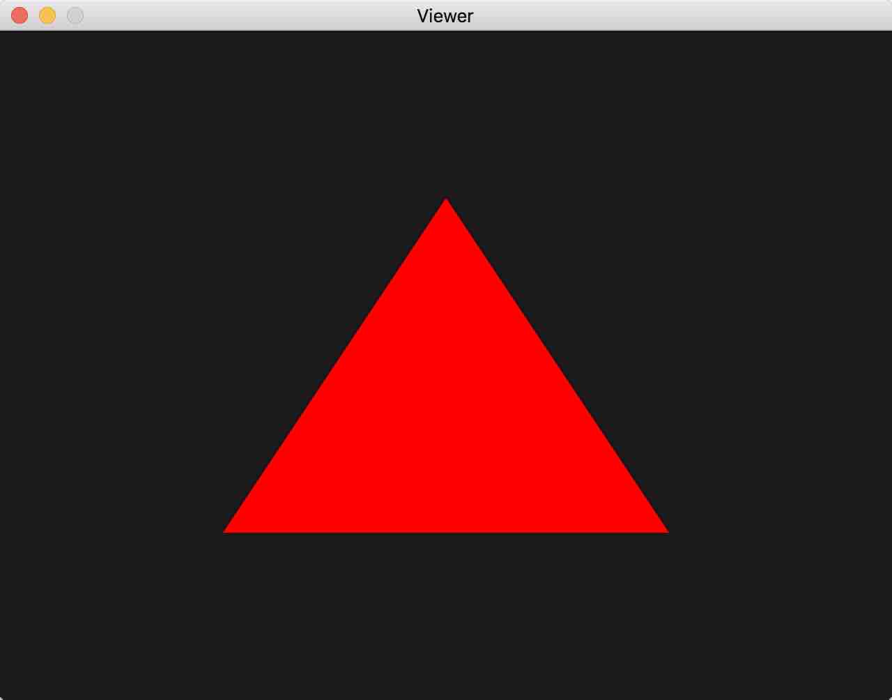
If all goes well, you should be getting this window.
Examining the Python code
A graphics application usually has the following basic structure:
Create a window and OpenGL context (active set of rendering states)
Initialize OpenGL render state
Setup our render scene and objects, upload their resources to GPU
Run an infinite render loop which draws the scene and processes events, with the following steps:
Clear the screen
Update scene state and draw our scene objects
Swap the draw and the viewed buffers for seamless transitions (more below)
Process events (keyboard, mouse…) for user interaction
Cleanup on exit
The rendering loop 4 is thus at the heart of the application and everything else before is there to prepare for it.
Flatly following the structure above in a program is OK for small scenes, but it
would be cumbersome as soon as we have several objects in a scene. Thus scenes
are usually broken down in objects with their own state, initialization and
draw code. This is what we did here for the Triangle class
of objects.
We also abstract the application window with its OpenGL state initialization
and rendering loop as the Viewer class. Scene objects can be added to
its list of render objects using its add() method, as seen in the
main() entry point:
def main():
    viewer = Viewer()
    color_shader = Shader("color.vert", "color.frag")
    viewer.add(Triangle(color_shader))
    viewer.run()
Objects added are to be drawn with a shader, which is the code to be executed
on GPU. Shader code needs to be compiled, linked, checked and uploaded only
once to GPU for later use throughout the application. For this we provide a
helper class Shader. Its initializer gets passed a pair of shader
source files for a vertex shader, the code that the GPU will execute at every
vertex primitive passed, and a string for the fragment shader,
the code the GPU will execute at every fragment (= pixel candidate).
We will explain shaders in greater detail GPU-side code.
Let us describe how the 5 main steps introduced above materialize in the code:
1. Create window and context
Creating the Viewer() object invokes the Viewer initializer
__init__().
It uses GLFW to create a system window and an OpenGL context associated to
that window, which is basically a set of internal OpenGL draw states used for
drawing in that window. It then makes that context active so subsequent OpenGL
commands modify that particular set of states:
glfw.window_hint(glfw.CONTEXT_VERSION_MAJOR, 3)
glfw.window_hint(glfw.CONTEXT_VERSION_MINOR, 3)
glfw.window_hint(glfw.OPENGL_FORWARD_COMPAT, GL.GL_TRUE)
glfw.window_hint(glfw.OPENGL_PROFILE, glfw.OPENGL_CORE_PROFILE)
glfw.window_hint(glfw.RESIZABLE, False)
self.win = glfw.create_window(width, height, 'Viewer', None, None)
glfw.make_context_current(self.win)
Hints tell GLFW to initialize the window and context with certain characteristics, such as using OpenGL 3.3 or more for our context.
2. Initialize OpenGL render state
The Viewer.__init__() initializer also contains code for one-time
OpenGL application state settings, such as initializing the OpenGL clear
color:
GL.glClearColor(0.1, 0.1, 0.1, 0.1)
3. Setup our scene objects
After the call to the initializer, objects can be added to the scene, with
their initializer setting up its specific OpenGL state. As in the
Triangle example provided, this typically consists in loading
an OpenGL Vertex Array to the GPU, basically an array of user
defined vertex attributes that will be needed to transform and draw the
object. Here we use only one attribute in the Vertex array, the vertex
position containing the three 3D coordinates of our
triangle vertices:
        # triangle position buffer, Numpy array of our 3D coordinates
        position = np.array(((0, .5, 0), (.5, -.5, 0), (-.5, -.5, 0)), 'f')

        self.glid = GL.glGenVertexArrays(1)  # create OpenGL vertex array id
        GL.glBindVertexArray(self.glid)      # activate to receive state below
        self.buffers = [GL.glGenBuffers(1)]  # create buffer for position attrib

        # create position attribute, send to GPU, declare type & per-vertex size
        loc = GL.glGetAttribLocation(shader.glid, 'position')
        GL.glEnableVertexAttribArray(loc)    # assign to position attribute
        GL.glBindBuffer(GL.GL_ARRAY_BUFFER, self.buffers[0])
        GL.glBufferData(GL.GL_ARRAY_BUFFER, position, GL.GL_STATIC_DRAW)
        GL.glVertexAttribPointer(loc, 3, GL.GL_FLOAT, False, 0, None)
4. Rendering loop
Once all this setup work is done, the render loop can be executed
using the call to Viewer.run(), with exactly the four steps
a, b, c, d we introduced above:
while not glfw.window_should_close(self.win):                      # while no close requested
      GL.glClear(GL.GL_COLOR_BUFFER_BIT)                           # a. clear the screen
      for drawable in self.drawables:                              # b. draw scene objects
          drawable.draw(...)
      glfw.swap_buffers(self.win)                                  # c. double buffering swap
      glfw.poll_events()                                           # d. process system events
First we need to clear the screen with the previously defined clear color to start with a fresh frame (else we would get pixels from the previous frame)
The only assumption we make about drawables is that they have a parameter-compatible
draw()method. For now we are just drawing our triangle object in theTriangle.draw()method. For this we need to tell OpenGL what shader to use, which vertex array to use, how the vertices in the array will be assembled to actual primitives (here aGL_TRIANGLEtag means we’re flatly describing an array of triangles, one triangle per group of three vertices in the array), and how many vertex primitives are in our original array (3 vertices, thus describing one triangle):def draw(self): # use shader, draw triangle as GL_TRIANGLE vertex array, draw array call GL.glUseProgram(self.shader.glid) GL.glBindVertexArray(self.glid) GL.glDrawArrays(GL.GL_TRIANGLES, 0, 3)
This code therefore results in calls to the code of the
self.shadershader program, which we will discuss in more detail below with the GPU-side code section.The classic double buffering strategy in computer graphics is as follows: to avoid displaying partially drawn frames which would result in flickering and visual artifacts, we always render to a back buffer while a finished front buffer is displayed, and swap the back and front buffer once drawing the back buffer is complete. GLFW transparently creates the two buffers when intializing the window.
We can process our own events in event handlers, as shown with
Viewer.on_key()to process user keystroke events, as long as the handler is registered to our GLFW window in the initializer. The handler gets notified during the main loop’sglfw.poll_events()call.
5. Cleanup
OpenGL requires explicit cleanup calls to
release previously allocated objects using their id. We take advantage of
Python classes and their destructors so that such cleanup is automatically
executed when the Python object is destroyed / unscoped, for the Shader or
the Triangle class of objects, as shown below:
    def __del__(self):
        GL.glDeleteVertexArrays(1, [self.glid])
        GL.glDeleteBuffers(1, self.buffers)
Keep in mind that the Python version of these calls takes an iterable (here
we stored them as a list) of index objects, which is why we used
[self.glid] to put the single Vertex Array id in a list here.
Note
The OpenGL context must exist when these destructors are called since they contain OpenGL calls. If you try to make calls to OpenGL code before or after the life of your OpenGL context, you will get exceptions.
This is why we put the general GLFW initialization and termination at the
topmost, global scope of the script, such that any objects added in the
main() function or subcalls are sure to be destroyed before the
glfw.terminate() call, which destroys our OpenGL context:
if __name__ == '__main__':
    glfw.init()                # initialize window system glfw
    main()                     # main function keeps variables locally scoped
    glfw.terminate()           # destroy all glfw windows and GL contexts
GPU-side code
GLSL code is given for the two main stages, the vertex shader, and fragment
shader stages. Additional stages exist but are optional, in fact we will not use
them in these practicals. Version 330 shaders and beyond all receive a
pre-processor #version directive declaring the compability information
of the shader code.
Vertex shader
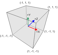
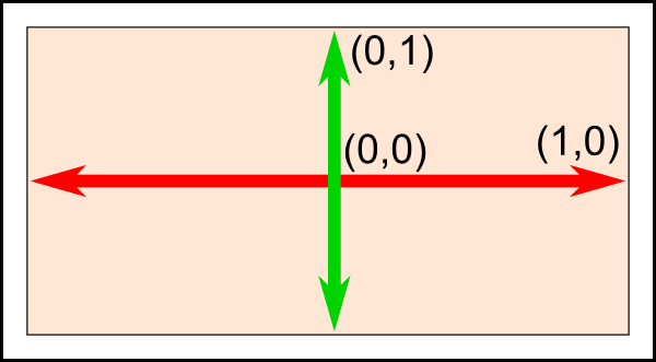
The vertex shader describes how each vertex is transformed to the homogeneous 4-vector clipping coordinates of the camera (aka normalized device coordinates), between -1 and 1 in every first 3 dimensions, and performs any per-vertex computation that may be useful for drawing.
|
Clip volume in normalized device coordinates |
Normalized screen coordinates |
The clip coordinates of the vertex are to be stored in a GLSL
built-in variable gl_Position.
For now our shader assumes we already give it clipping coordinates and store it
as the result directly:
#version 330 core
in vec3 position;
void main() {
    gl_Position = vec4(position, 1);
}
The vertex shader receives the per-vertex attributes that were passed when the
above vertex array was created for intended use with this shader. Vertex
attributes received from CPU arrays are tagged with the in qualifier. Here
only one attribute is passed, position. vec3 indicates that its
type is a 3x 32-bit float vector. The call to
loc = GL.glGetAttribLocation(shader.glid, 'position') allows to retrieve
the location of the shader variable position. This location allows to pass
the array content from the CPU to the right shader variable, first by enabling
with the glEnableVertexAttribArray(loc) function call. Second,
the location is also used as the first parameter of
glVertexAttribPointer(loc,...) that specifies which
array data to pass from Python code to GPU.
Notice that since we pass position\(\in \mathbb{R}^3\), we need to
extend it as vec4 with a unit scale factor, since gl_Position
expects a \(\mathbb{R}^4\) homogeneous 3D vector.
Fragment shader
The fragment shader describes how a fragment is to be drawn. A fragment is a pixel candidate, meaning it outputs a value for a pixel, which may still be overwritten. A given pixel in a drawn frame may have had several fragment calls.
The given fragment shader first declares what variable will be used to store the
output color to be used for drawing the fragment (here outColor).
It must be a 4 dimensional vector of floats \(\in [0, 1]\), the first 3
being the RGB color and the fourth an alpha transparency value we will use
later on and keep to one for now. The given shader just uniformly draws
pixels in red:
#version 330 core
out vec4 outColor;
void main() {
    outColor = vec4(1, 0, 0, 1);
}
Exercises
1. Playing with the shader
The red color is currently hardcoded in the fragment shader. Change the triangle color to green, blue.
Try adding constant offsets on x, y and z, to the output clip coordinates in the vertex shader. What happens when your triangle goes beyond the clipping coordinate limits?
2. Color as shader uniform
Let’s pass the triangle color as a program parameter.
OpenGL allows to pass user defined shader global parameters, called uniform variables. Global means they are to be specified only once per shader for all vertices and fragments, per primitive, object or even once per frame, depending on intended use. Syntaxically, in the vertex or fragment shader, you declare them in the prefix section of the shader with other variables, but with the uniform qualifier, as follows. For now, we will focus on passing just a color as vector of 3 floats to the fragment shader:
#version 330 core
uniform vec3 color;
out vec4 outColor;
void main() {
    ...
}
On the CPU side, to pass program values to this variable, you first need to
get its shader program location using glGetUniformLocation(),
basically an OpenGL id to address this variable.
Location queries use the program id returned
by a glCreateProgram() call, which is provided here by the member
glid of our Shader class in our framework,
and the string name of the variable to locate. Once the location is obtained,
you can proceed to send a Python triplet to the shader:
my_color_location = GL.glGetUniformLocation(self.shader.glid, 'color')
GL.glUniform3fv(my_color_location, 1, (0.6, 0.6, 0.9))
The suffix 3fv specifies that we’re passing a vector type (v) of three
floats (3f). (The second parameter of the glUniform3fv() call
specifies how many vector values you wish to pass: useful for arrays,
we don’t use this other than 1 for now).
Place the above Python code in the
draw()method of yourTriangleclassUse the value obtained in the shader as the ouput color of your fragment shader. Beware that you need to extend it to vec4 with 1 as last value to obtain a valid output color.
The above example is still a static color, even though passed from the CPU. Let’s make it more interesting: modify your
Trianglecode to initialize a color member in__init__(), and let the user modify it interactively by associating it to key events in a newly addedkey_handler()callback method of theTriangleclass.
3. Varying the color with position
Currently the vertex and fragment shaders are not communicating. The vertex
shader can output arbitrary values or vectors to the fragment shader, which will
receive an interpolated version of them. For this, the variable needs to be
declared with the out qualifier in the vertex shader, and in qualifier
in the fragment shader, with the same variable name.
Try passing down the clipping coordinates to the fragment shader, then use them to generate smoothly varying fragment colors. Try first replacing the output value with this new interpolated value, then try adding it to the uniform from the previous question to see the effect of both. What happens when generated colors get outside of their intended range \([0,1]\)? You can try applying offsets or functions to your color vectors to keep them smoothly varying in that range.
4. Colors as vertex attributes
Directly inferring the color from clipping coordinates is quite constrained and
mostly for demonstration purposes.
Let’s try passing per-vertex colors as user-defined attributes. For this you
will need to reproduce all the steps that exist in the code for the
position attribute, for a new attribute color:
Modify the initializer of the
Triangleclass to add a second vertex buffer to our vertex array. Pass it a numpy array of 3x 3-vectors for user-defined vertex colors, for example red, green and blue, and assign it to the layout index 1.Warning
The layout index appears as the first parameter of both the
glEnableVertexAttribArray()andglVertexAttribPointer()functions. Also,glGenBuffers()returns a scalar index value when used with argument one (glGenBuffers(1)) but returns a list of indices when used with argument > 1Modify the shader program to receive the new attribute and also pass an interpolated version of it from vertex to fragment shader (replacing your previous interpolated variable).
Don’t forget to make sure the newly created vertex buffer is in the list of buffers to be destroyed in the object finalizer!
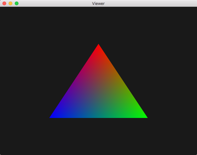
What you should get when assigning red, blue and green as vertex attributes
5. Object Transforms
We made great progress on shaders but our scene is quite static still and up to now only expressed in clip space \([-1, 1]^3\). We need the ability to reposition objects and express them in any metric. Recall that 3D points are expressed in homogeneous coordinates with 4-vectors \(\in \mathbb{R}^4\). So all rigid or affine 3D transforms \(\mathbb{R}^4 \rightarrow \mathbb{R}^4\), are expressed as \(4 \times 4\) matrices.
For convenience we provide a small Numpy-based transform module to experiment
with, to be placed in the same directory as viewer.py:
You can take a look at the matrix functions as they are pretty straightforward.
Let us only focus on basic transforms for now, by including this at the
beginning of the viewer.py file:
from transform import translate, rotate, scale, vec
Let’s apply these transforms to the rendered object in the shader. Let us first consider rotating the object around the origin of the clip space.
First, similarly to 2. Color as shader uniform, you want to modify your Python
Triangle.draw()method to pass a \(4 \times 4\) rotation matrix, here a 45 degree rotation around y axis for example:matrix_location = GL.glGetUniformLocation(self.shader.glid, 'matrix') GL.glUniformMatrix4fv(matrix_location, 1, True, rotate(vec(0, 1, 0), 45))
Sidenote: the third boolean parameter
Trueindicates that the matrix is passed in row major order, which is how Numpy stores bi-dimensional matrix arrays.Second, modify your vertex shader, to receive this matrix uniform, and use it to transform the position of each vertex. Position being a
vec3, it needs to be extended to a vec4 homogeneous vector of scale 1:uniform mat4 matrix; in vec3 position; ... void main() { gl_Position = matrix * vec4(position, 1); ... }
On the Python side, try to pass different rotations, try applying
scale(), and then try composing both a scale and a rotation. You can compose transforms in Python using thea @ bmatrix multiplication operator over Numpy arrays.Warning
a * bon Numpy arrays is the coefficient-wise product, not the matrix productNow use
translate()to pass a translations to the shader. What happens if you translate the object along z only? You can try composing it with a rotation and scale as well.
6. Projection Transform
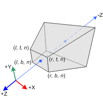
The reason for what’s happening in the last question is: there is no foreshortening in our model yet. Once in normalized device (or clipping) coordinates, OpenGL just retains the x and y components for rendering, which amounts to a 1:1 orthographic projection. Let’s add perspective projections to our program to have renderings that mimic real cameras:
|
Frustum clipping volume in camera coordinates before projection |
Clipping volume in normalized device coordinates |
For this, we have the perspective() function from the
transform.py module, parameterizing the frustum
using its vertical field of view in degrees and the camera aspect ratio
(width / height in pixels), and both a near and far parameter
indicating the distance from the front and back clipping planes of the frustum.
first import it from the transform module:
from transform import perspective
experiment with the function. For this you need to compose the projection matrix with a view matrix ( = camera placement matrix) translating the triangle such that it is inside the clipping planes of the frustum.
Question: what is the right matrix multiplication order to apply to the projection and view matrices here?
There are two ways to obtain the product of the projection and view matrices in your shader:
Either pass both the projection and view matrices to your shader as uniforms and perform a matrix multiplication at each vertex with the GLSL * matrix product operator
Or, as in the previous question, compute the product on the CPU-side with the dedicated Numpy matrix product operator
a @ band pass the result in one uniform matrix.
Elements of solution
You can check you results against these solution files:
viewer.py
color.vert
color.frag
We gained understanding of how to pass variables, attributes and
transforms, and use them in the shader. Regarding transforms, as seen in the
course, actually three types of transforms are used in practice:
projection, view, and model, which will later be passed to all objects
during the draw() method call.
We’ll come back to those in more detail in
Practical 3 - Hierarchical modeling.
